
Figure 1: Some example viewpoints on the concept "heat exchanger" see from various applications in an oil production process application
1LABEIN, Parque Tecnologico, Ed. 101, 48016 - Zamudio Bizkaia, Spain. E-mail: {lares,amaia}@labein.es
2University of Amsterdam, Department of Social Science Informatics, Roetersstraat 15, NL-1018 WB Amsterdam, The Netherlands. E-mail: {anjo,schreiber,wielinga}@swi.psy.uva.nl
3IBERDROLA, Gardoqui, 8, 48008 - Bilbao, Spain. E-mail: jose.corera@iberdrola.es
From a practical point of view, the objective of the KACTUS project is to develop a number of reusable ontologies for technical systems, together with methods and tools for using these ontologies in practical applications. Application domains in this project included ship design, oil platforms, and electrical service networks. The project was driven by the user needs of the application partners involved. The application tasks involved were typically complex knowledge-intensive ones such as service-recovery, procedure generation, simulation, design etc.
In Section we briefly discuss data models and their limitations in the context of reusing complex technical information found in the domains we have tackled. We see ontologies as a "natural next step" in the increasing complexity of data models, and propose in Section a framework for knowledge reuse, that can be used as an add-on to existing system development approaches such as CommonKADS or STEP. One central theme in the KACTUS approach is the construction of libraries of ontologies. We briefly discuss the organization principles of such a library based on the library we constructed within the project.
Section describes a small experiment we performed to test the KACTUS approach in the electrical network domain. This experiment involved the construction of a demonstrator within the time scale of one week, reusing an existing ontology of an electrical network. This experiment shows how a shared ontology can be used for interoperability. In this case existing databases about the static and dynamic structure of the network could be integrated in the application in a principled way. Section reflects on the results of this experiment and discusses related work.
Since then, many extensions have been proposed to the ER scheme. All these extensions aim at providing more powerful ways of capturing the meaning ("semantics") of the data described by the model. A common extension is the use of sub-class hierarchies of entity classes, capturing commonalities between entities in different classes. There is currently a whole literature on semantical constructs that could be used in data models ("semantic data modeling", "extended ER modeling", "hyper-semantic data modeling").
A good example of a contemporary extended ER data modeling scheme can be found in the OMT approach (Rumbaugh et al., 1991). OMT provides, amongst others, the following data modeling primitives:
However, if one wants to reuse a notion like "heat exchanger", it quickly becomes clear that this term can have different meanings in different contexts (see Figure 1). For example, from an oil-platform design perspective the physical properties will be the main emphasis: physical dimensions, types of connections, etc. In a diagnostic setting functional properties such as the difference in temperature between the different inputs and outputs are likely to be the prime focus of attention. For dynamic simulation applications, behavioral properties such as mathematical properties of the heat exchange process would need to be modeled in association with "heat exchanger".

Figure 1: Some example viewpoints on the concept "heat exchanger" see from various applications in an oil production process application
It is safe to say that reuse of complex, knowledge-intensive data is impossible without taking these different viewpoints into account. This means that we want to be able to look at a data type like "heat exchanger" in different ways. This idea is partially present in the ANSI/SPARC architecture of databases (see Figure 2). This architecture consists of three levels:
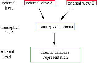
Figure 2: ANSI/SPARC architecture
The ANSI/SPARC external views can be used to some extent for the representation of the different viewpoints, such as those on a "heat exchanger". The main limitation is that the viewpoints themselves do not add new information: all basic information is already present in the conceptual schema. This is not the case in most realistic situations: each viewpoint on an object adds its own context-specific information items, and there is not one universal unified representation for all the viewpoints. Such a unified representation is impossible because the number of viewpoints one can take is in practice unlimited. In other words, objects like "heat exchanger" can be used in so many different contexts that it is impossible to develop in advance a complete, unified description of a "heat exchanger" that will prove to be sufficient for every possible situation.
This observation about viewpoints on real-world objects lies at the heart of the KACTUS project. We have formulated this as a major principle underlying the KACTUS approach:
Principle 1: The representation of real-world objects always depends on the context in which the object is used. This context can be seen as a "viewpoint" taken on the object. It is usually impossible to enumerate in advance all the possible useful viewpoints on (a class of) objects.
This principle has important consequences for an approach to reusing knowledge-intensive information items. It means that it is not feasible to strive for one unified representation, that can be used in multiple application settings. Typically, one would expect that application descriptions can be partially reused in another setting, namely exactly those descriptions that share a common viewpoint. For example, in the electrical network domain, the functional model of the network built for a diagnostic application might also be useful for a service recovery application, whereas some other knowledge items are likely to be application-specific for a diagnostic context.
It should have become clear by now that in the KACTUS view the key to reuse lies in explicating the underlying viewpoints of a representation. This can be seen as the second principle underlying the KACTUS approach:
Principle 2: Reuse of some piece of knowledge requires an explicit description of the viewpoints that are inherently present in this knowledge. Otherwise, there is no way of knowing whether, and why this piece of knowledge is applicable in a new application setting.
For arriving at such an explicit description of viewpoints, the notion of "ontology" is introduced.
Two features are typical of ontologies: the fact that there can be multiple ontologies (= viewpoints) on the same domain, and the fact that we can identify abstraction levels of ontologies on top of each other. We discuss both features in more detail:
Multiple ontologies Assume we have some artifact such as a ship. One can define multiple viewpoints on a ship. Well-known examples of such viewpoints are the physical structure ("what are the parts of a ship?") and the functional structure ("how can a ship be decomposed in terms of functional properties?"). Although these two viewpoints often partially overlap, they constitute two distinct ways of "looking" at a ship. The purpose of an ontology is to make those viewpoints explicit. For a design application, such as a CAD application, one would typically need a combined physical/functional viewpoint: a combination of two ontologies. For a simulation application (e.g. modeling the behavior of a ship) one would need an additional behavioral viewpoint. Many other viewpoints exist such as the process type in the artifact (heat, flow, energy, ...). Each ontology introduces a number of specific "conceptualizations, that allow an application developer to describe, for example, a heat exchange process. As stated earlier, the main observation that lies at the heart of KACTUS is the observation that for reuse it is necessary to make these viewpoints explicit.
Levels of ontologies Ontologies are not just a flat set of descriptions of conceptualizations. Typically, one can identify several levels of abstractions on which ontologies can be defined. For example, in an electrical network domain we could have a set of ontologies of an electrical network in the Basque country in Spain, describing how the various sub-stations and their sub-parts together make up a network. We can first try to generalize from this "Basque" ontology, and try to come up with ontologies for electrical networks in general. A second generalization step would be to define for those ontologies describing electrical processes in the network a general ontology for electricity processes, independent of whether it is a electrical network or some other artifact in which the process takes place. Yet another level up, we can think about general categories of knowledge structures. What are the general characteristics of things that we can structurally divide up in parts? Or of connections between components?
As we will see in the next section, these generalization levels provide us with a useful typology of ontologies, that can be used an organizational principle for a library of ontologies. If we characterize ontologies using the multiplicity and abstraction features we end up with a whole network of ontologies, with many interrelations. At this point one might think that we are becoming overly ambitious here. It is clearly not feasible to try to describe the whole physical world in terms of ontologies. Philosophers have tried to do this for ages, and have not come up with complete categorizations of the world. As will become clear, KACTUS solves this problem by taking a pragmatic, bottom-up approach to ontology identification, in which use and reuse of an ontology in applications is the main criterion. Also, limiting ourselves to technical artifacts makes life a bit easier.
Typical additional language primitives include:
In KACTUS we selected three ontology specification languages for usage in the project, namely the STEP modeling language EXPRESS (Spibey, 1991), the CommonKADS modeling language CML (Schreiber et al., 1994), and the Ontolingua language (Gruber, 1993) developed in the context of the US knowledge sharing effort. This choice was based on the following grounds:
The choice for these three languages is thus primarily pragmatic. Other languages including advanced data modeling languages such as the proposed in the "Unified Method" of Rumbaugh and Booch could serve a similar purpose. The key lies in the content of what is represented in an ontology, not in the representational syntax used[1].
The use of multiple languages has made life more difficult for the KACTUS tools. The toolkit constructed within KACTUS had to have facilities to cope with this variety of languages in a consistent and transparent way. A discussion on the tools is however outside the scope of this paper (see http://www.swi.psy.uva.nl/projects/void/roadmap.html for a description of the functionality of the toolkit).
Central is the role of a library of ontologies. This library contains a number existing definitions organized along the levels of abstraction described before. Three types of ontologies are placed in the library: domain ontologies, basic technical ontologies and generic ontologies. As application ontologies are considered specific for a particular application, these are not stored in the library. shows the features that were used to index the ontologies in the library. The KACTUS toolkit supports searching for ontologies using these features, and also supports searches for names of individual definitions.
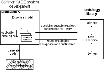
In KACTUS we have constructed a library containing the ontologies used in the technical domains the project is concerned with. However, we do not assume that there should be just one large library. Typically, companies/organizations will want to set up their own shared set of ontologies.
KACTUS sets out to support four types of activities (see the four arrows in Figure 3):
Typically, application development is in fact a combination of ontology construction and reuse. Some ontologies already exist and can be taken from a library. Other required conceptualisations might not be provided by the library, and have to be constructed from scratch.
The KACTUS toolkit provides facilities for importing, organising, merging, editing, and exporting ontologies in the three languages used in KACTUS (EXPRESS, CML and Ontolingua). In addition, knowledge bases containing "instances" of the definitions present in an ontology can be imported, stored and exported.
Index feature
|
possible
values
|
| used
in application
|
<application
name>
|
| used
by task type
|
diagnosis,
design, configuration, assessment, planning, scheduling, prediction,
assignment, ...
|
|
used by problem-solving method
|
systematic
diagnosis propose-and-revise
......
|
|
used in domain
|
oil
production process ship design
electrical network
|
Table 1: Indexing features for ontologies in the library
One feature of the approach is that it provides a principled way for supporting interoperability of applications through exchange of knowledge or complex (semantically rich) data. This type of interoperability is shown schematically in Figure 4. If one can assume that two applications share the same ontology (which is typically a sub-part of the overall application ontology of an application), then the two applications can exchange information that is based on this shared ontology. The exchange procedures can be very simple or elaborate, depending on the differences in implementation-specific representation choices, but the application developer can be sure that information exchange is always technically feasible. A number of examples of exchange based on shared ontologies exist. For example, in the Sisyphus-VT experiment (Schreiber & Birmingham, 1996) several contributors were able to reuse an existing knowledge base of elevator components and constraints in their application, even if their application was written in an entirely different implementation language. Typically, each application added its own application-specific conceptualizations, based on the different ways in which the design task was realized. Ontologies served the role of explicating which parts of an application knowledge base can be shared, and which parts cannot.
In the ship-design domain in KACTUS this "shared ontology" approach is used to enable the exchange of ship-design data between the ship designers and the ship assessors, although designers and assessors have quite different ways of "looking" at a ship design. More details on this application can be found in Martil et al. (1995). In the next section an experiment is described in which a small application is built in a short time-frame (one week), in which data/knowledge exchange based on a shared ontology is the key issue.
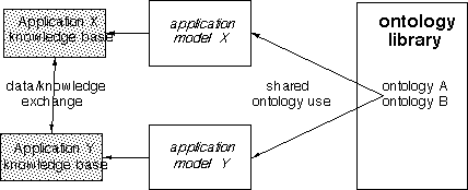
Figure 4: A schematic description of how interoperability between applications can be achieved. The two applications use the same set of ontologies in their application analysis model (e.g. a CommonKADS expertise model or a STEP application protocol). Each application typically also has additional ontologies, but uses the shared ones to exchange data between applications.
To perform the reconfiguration, operators first need to know whether the fault is temporal or permanent. If a fault is permanent, the equipment at fault is damaged and it requires sending a maintenance crew into the field in order to repair it. As a consequence, the equipment cannot be used during reconfiguration. If, on the other hand, a fault is temporal it disappears after a while, and no equipment is damaged. In this case the equipment at fault can be put into service again and the state of the network previous to the fault can be recovered.

Figure : Duero area 132 kV network. Ovals denote substations (e.g., Ricobayo at the top-center), squares with a twiddle and a number denote generators and their number, lines between ovals denote electrical lines, and the small circles hanging from the substations denote transformers
At the point in time when an operator has to decide whether a fault is temporal or permanent, the equipment at fault has been isolated automatically by the protective equipment in the network. This means that the operator does not get information about the state of the equipment from the data acquisition system SCADA (Supervisory Control And Data Acquisition system). Also, information about loads has been lost. In this situation, there are only two ways to find out know what the actual state of the equipment is. One way is to send a crew into the field to inspect the equipment and report back. The time and advanced planning required to do this makes this solution unattractive. The second solution involves assuming that the fault is temporal, and putting the equipment (previously at fault) into service again. If, after putting it into service, the protective equipment isolates the faulty equipment again, it means that the previous fault was permanent and the equipment cannot be used for reconfiguration. Although more risky because of potential additional damage, this second solution is sometimes considered feasible by the electrical companies, and it is the one generally adopted. When putting the equipment into service, the electrical utilities have established a strategy to minimize the risk of damaging the equipment or endangering the stability of the network. This strategy has to be followed by the operators when generating procedures for testing damaged equipment.
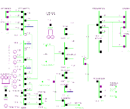
Figure 6: Exact reproduction of the display that operators get on their screen when requiring details of the Duero 132 kV network. Anecdotally, this display covers not just the 132 kV Duero network (shown on the middle-left side of the display) but also part of a 132 kV area not belonging to Duero (right side of the display). Black squares are closed breakers, and white squares are open breakers. The numbers are values of voltage and power flow. Thicker lines are bus-bars, and thinner ones are electrical lines. Circles with a G inside are Generators, and arrows going out of breakers are loads (or consumers).
The objective of the system built in this experiment is to automate the generation of procedures for testing equipment at fault, following the strategy established by the electrical utilities. The output of the system should be the actions an operator has to follow to perform the test.
Once a suitable problem was identified, the next step was to restrict the scope of the problem, such that it would still be a real-world problem and at the same time feasible to tackle within a limited period of time. In terms of the electrical network controlled by Iberdrola, the scope of the system is the 132 kV network in the Duero region (see Figure 5). This network is spread over 72.000 km2 (one seventh of the Spanish territory). In terms of size, it is approximately 5% of the high voltage network controlled by Iberdrola. This is a real network, and we have taken into account real power measurements (although they are not taken on-line). Figure 6 shows a display with further details of substations and equipment in this network area.
The system implements the strategy established by the electrical utilities to test equipment at fault and generates testing procedures for operators to follow. This strategy is described in Appendix A. Figure 7 shows the inputs and outputs of the system.
The system should get three inputs:
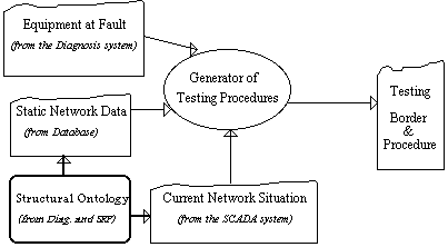
Figure 7: System inputs, output and interoperability with other systems. The structural ontology is used by the diagnosis system as well as the generator of testing procedures (see the next section for a description of the ontology and how it is used by the application).
The system has three outputs: the testing border[2] candidates, i.e., the nodes from which energy could be supplied to the faulty equipment during the test; the best testing border, i.e., the node from which energy should be supplied to the faulty equipment during the test to minimize the risk of damaging other equipment or endangering the stability of the network; and the testing procedure, i.e., the opening and closing operations that have to be performed by the operator during the test to supply energy to the faulty equipment and see if the equipment is operational again.

Figure 8: The set of ontologies build for the service recovery and diagnosis applications. These ontologies reside in the KACTUS library.
First, a mapping was developed from the ontology to the static network data (the first input to the system). The static network data resided in a Iberdrola company database, and used the Spanish language. The two translate processes at the left of Figure 9 transform the data from the database format into the ontology instance format: first from the database format to Prolog (the chosen implementation language) and then from Spanish to English. The instantiate process maps the instances produced by the translate steps onto the ontology. This process generates a number of new instances that can be derived from the axioms in the ontology. For example, the ontology defined how equipment could be associated with other equipment: background knowledge which is relevant for the application. These new data are in fact data that were implicit in the original database. Subsequently, the dynamic network data (the second and third inputs) are read in. These data are obtained from the SCADA system and are also mapped into ontology instances. The full set of input data, now represented as ontology instances, is then read into the application.
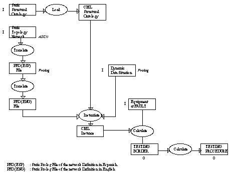
Figure 9: Steps taken to design and build the application reusing the structural
ontology from the KACTUS library. Inputs to the system are signaled by an
I on their left hand side, and outputs by an O underneath.
Figure 10 shows the contents of the "structural-ontology" which has been renamed to "electrical-structural-ontology". The hierarchy shows the different kinds of "static-equipment" used by the application and the drawing shows the relations between "bus-bar" and other concepts. The relation "connected-to" means that a "bus-bar" can be physically connected to another equipment. The relation "current-connection" means that there can be an energy flow to other equipment.
In Appendix B excerpts from the original data and the way these are processed can be found, to illustrate the transformation process described in Figure 9.
Once all aspects related to the input of static and dynamic network data were implemented and installed (with the help of the KACTUS toolkit as mediator), the rest of the system was implemented and tested. This implementation contains two parts: a simple graphical user interface and the implementation of the two main algorithms: (i) choosing the best border from which the equipment at fault should be energized, and (ii) the generation of the testing procedure. A snapshot of the running system is shown in Figure 11.
The system was developed in XPCE-Prolog and it was tested until the results obtained were considered satisfactory. Satisfaction in this case, means that having tested 80% of the data, all the testing borders and procedures given by the system are correct. It should be pointed out, however, that further testing by users from Iberdrola is required to tune the values of the constants that are used in the algorithm (i.e., the "magic numbers" drawn from experience, see Appendix A).
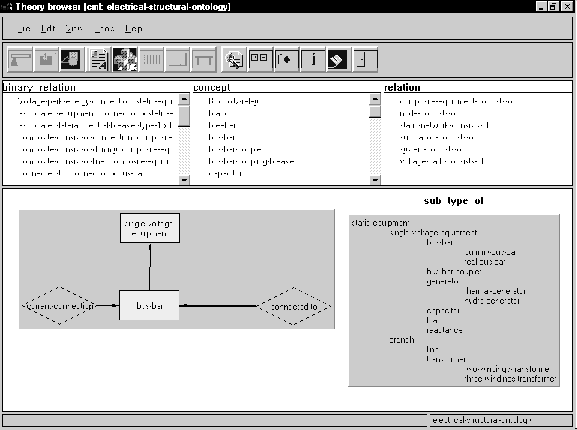
Figure 10: This figure shows the theory browser of the KACTUS toolkit. The browser displays the contents of the "structural-ontology" which has been renamed to "electrical-structural-ontology". The hierarchy shows the different kinds of "static-equipment" used by the application and the drawing shows the relations between "bus-bar" and other concepts. The relation "connected-to" means that a "bus-bar" can be physically connected to another equipment. The relation "current-connection" means that there can be an energy flow to other equipment.
An important point to make is that the prototype had two main purposes. The first purpose (highlighted in this paper) is to illustrate the use of the KACTUS framework for reuse. The other, important purpose from Iberdrola[yen]s point of view, was to develop a prototype that could be used as a workbench to tune the testing procedure before implementing it as a final on-line application. The result met both objectives.
Re-using the structural electrical ontology for this experiment highlighted the distinction between static and dynamic knowledge. In this application, the concept node, which is a subtype of a compound structure according to the static definition of the network in the structural ontology, is a dynamic entity, and therefore it makes no sense to include it in the static definition of the network. This is why the static input data from Iberdrola[yen]s database do not include instances of the concept node. However, this conceptual mismatch has severe consequences for the reasoning process in this application (and probably others since this is a concept used in several applications).
KACTUS methods, and in particular methods to reuse an ontology from the ontology library, were used as an add-on to system-development. The electrical network domain ontology was reused to generate the application knowledge base. However, during the system development we did not generate an application ontology, mainly due to time constraints. This does not mean that an application ontology would not have been useful. Concepts such as testing border, procedure, source of energy, permanent fault or temporal fault would be part of such an application ontology. This ontology could have been a possible reusable ontology constructed from the application and to be included in the library.
Interoperability was also illustrated in this experiment. Five applications (Diagnosis, Service Recovery Planning, the Database, the SCADA, and the Generation of Testing Procedures) share the same structural ontology of the electrical network. Each application also has additional ontologies, but uses the shared ones to share data between the applications.
There are two important aspects to consider within an ontology based framework for reuse. Firstly, a clear organization of an ontology is needed. The ontology may be used by persons that do not know very well the knowledge it contains. In this case, the use of a clear methodology in its derivation is essential to make the knowledge understandable to non experts in the field.
Secondly, reuse is almost never complete. Re-use of any ontology, for different purposes than those for which it was built, will always require modifications or tuning for the new purposes. If these modifications are not performed in a systematic way, reuse of the new ontology is likely to turn out to be difficult.
The approach in which data and/or knowledge are exchanged through a shared ontology has also been applied by some contributors to the Sisyphus-VT experiment. This paper shows in fact another example in which this method for interoperability proves to work. Although the method is simple, the users (in this case, the Iberdrola people) were surprised by the efficiency in which data from other applications could be used in a new application.
The idea of generating an application ontology from other, more reusable ontologies is also present in the PROT...G...-2 approach (Gennari et al., 1994). In their approach, the application ontology is generated from a mapping between a domain ontology and a "method ontology": the representations required by the problem-solving method chosen to solve the task. The main difference is that KACTUS is focused on specifying on the nature of domain ontologies: organizing these ontologies in a library, and in levels of abstraction. In this sense the approaches are complementary, similar to the relation between KACTUS and CommonKADS.
This work also differs from other work on ontologies such as Guarino et al. (1994), because the approach towards ontologies is much more pragmatic. The scope of the KACTUS library is limited to technical domains. Also, the generic ontologies in KACTUS(not discussed in this paper, but see Benjamin et al., 1996) have a different status: these are not meant to provide a more or less complete set of categories to carve up the world. but rather act as useful abstractions of phenomena encountered in technical domains.
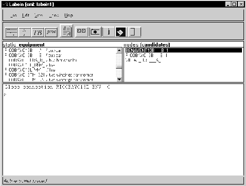
Figure 11: Snapshot of the demonstrator. Bus-bar A in Ricobayo (top-center in Figure 5 and bottom-left in Figure 6), named RICOBAYO13B_A, is at fault, the system provides as testing border candidates RICOBAYO13B_B_1 (node containing bus-bar B in Ricobayo), BENAVENT13B_B_1(node containing bus-bar B in Benavente), and VILLAL_I13B_A_1 (node containing bus-bar A in Villalcampo I), all of which are connected to RICOBAYO13B_A_1 Out of these, the system selects as the best testing border BENAVENT13B_B_1. At this point the dynamic connections in the network are the following: the connections of bus-bar A in Ricobayo with the lines that go to the other substations (Benavente and Villalcampo I) are open because the protective equipment has opened them to isolate the fault detected in bus-bar A ("open" means that no energy flows through the connection). The connections of Benavente and Villalcampo I with Ricobayo are closed (energy flows though the connection) because the fault is already isolated in Ricobayo. The testing procedure, thus, involves allowing energy to flow only from the best testing border, BENAVENT13B_B_1, to the equipment at fault, RICOBAYO13B_A, and not from Villalcampo. The procedure only requires one operation in this case: "close connection RICOBAYO13L_BNV_C" which closes the connection between Ricobayo and Benavente to allow the flow of energy from Benavente to Ricobayo.
Acknowledgments We are grateful to all participants in the KACTUS project for the many discussions about the ontologies and reuse, which provided the basis for the work described in this paper. The research reported here was carried out in the course of the KACTUS project. This project is partially funded by the ESPRIT Programme of the Commission of the European Communities as project number 8145. The partners in the KACTUS project are ISL (UK), LABEIN (Spain), Lloyd's Register (United Kingdom), STATOIL (Norway), Cap Programmator (Sweden), University of Amsterdam (The Netherlands), University of Karlsruhe (Germany), IBERDROLA (Spain), DELOS (Italy), FINCANTIERI (Italy) and SINTEF (Norway). This paper reflects the opinions of the authors and not necessarily those of the consortium.
References
Benjamin, J., Borst, P., Akkermans, J. M., and Wielinga, B. J. (1996). Ontology construction for technical domains. In N. R. Shadbolt, K. O'Hara and A. Th. Schreiber (eds.) Advances in Knowledge Acquisition: Proceedings Ninth European Knowledge Acquisition Workshop EKAW'96, pp. 98-114, Lecture Notes in Artificial Intelligence, volume 1076, Berlin/Heidelberg, Germany, May 1996. Springer Verlag.
Bernaras A., Laresgoiti I., BartolomÈ N. and Corera J. (1996a). An ontology for fault diagnosis in electrical networks. In O.A.Mohammed & K.Tomsovic (eds.) .Proceedings of the International Conference on Intelligent Systems Applications to Power Systems, pp. 199-203, Florida, USA.
Bernaras A., Laresgoiti I. and Corera J. (1996b). Building and reusing ontologies for electrical network applications. In Proceedings of the European Conference on Artificial Intelligence, pp. 298-302, Budapest, Hungary.
Chen, P. P. S. (1976). The entity relationship model -- toward a unified view of data. ACM Trans. on Database Systems, 1:9--36.
Gennari, J. H., Tu, S. W., Rotenfluh, T. E. and Musen, M. A. (1994). Mapping domains to methods in support of reuse. Int. J. Human-Computer Studies, 41:399-424.
Gruber, T. (1993).A translation approach to portable ontology specifications. Knowledge Acquisition, 5:199--220.
Guarino, N., Carrara, M. and Giaretta, P. (1994). Formalizing Ontological Commitments. Proceedings AAAI'94, Seattle, Morgan Kaufmann.
Martil, R., Turner, T., and Terpstra, P. (1995). Knowledge Reuse in Technical Domains: The KACTUS Project. In Proceedings of The Impact of Ontologies on Reuse, Interoperability and Distributed Processing, Unicom Seminar, London.
Rumbaugh, J., Blaha, M., Premerlani, W., Eddy, F., Lorensen, W. (1991). Object-Oriented Modeling and Design. Englewood Cliffs, New Jersey, Prentice Hall.
Spibey, P. (1991).Express language reference manual. Technical Report ISO 10300 / TC184/SC4/WG 5, CADDETC.
Schreiber, A. T., Wielinga, B. J., Akkermans, J. M., Van de Velde, W., Anjewierden, A. (1994a). CML: The CommonKADS conceptual modeling language. In Steels, L., Schreiber, A. T., Van de Velde, W., editors, A Future for Knowledge Acquisition. Proceedings of the 8th European Knowledge Acquisition Workshop EKAW'94, volume 867 of Lecture Notes in Artificial Intelligence, pages 1--25, Berlin/Heidelberg. Springer-Verlag.
Schreiber, A. Th., Wielinga, B. J., Akkermans, J. M., Van de Velde, W., and de Hoog, R. (1994b). CommonKADS: A comprehensive methodology for KBS development. IEEE Expert, 9(6):28-37, December.
Schreiber, A. Th. and Birmingham, W. P (1996). The Sisyphus-VT initiative. Int. J. Human-Computer Studies, 44(3/4):275-280, March/April. Editorial special issue.
An equipment at fault is tested only if its recovery is essential to provide service to customers. Transformers, generators, and loads are not tested due to the economic impact that any damage to such equipment would produce. Under these restrictions the strategy for testing, also implemented in the system, is as follows:
1. Identify all the energised borders surrounding the equipment at fault.
2. Choose for testing, those borders that do not cause the loss of loads or generators.
3. If rule 2 does not apply, choose a border with hydraulic generators.
4. If rules 2 and 3 do not apply, choose the border that may cause the loss of the minimum industrial loads in MW.
After classifying the energized borders according to these criteria, the following preference rules are used to choose between equivalent options:
< Choose the border with the minimum short-circuit power.
< Choose for testing the border that connects the equipment at fault with the line of highest impedance (longest), if the equipment at fault is a bus-bar.
< Choose the border that is equipped with quick reacting protective relays.
After classifying the borders according to the criteria, their preference is established taking into account the existing configuration:
a) Choose for testing those borders whose configuration is of the type breaker and a half and test the equipment by closing the lateral breaker.
b) If rule "a" does not apply, then choose a double bus-bar configuration.
c) If rules "a" and "b" do not apply choose a single bus-bar configuration.
All the criteria can be compiled into the following formula:
TB = Kgl * (1000 * Thermal + 3 * hydraulic + 5 * SUM(loads)) + Ksip * ( (Pcc-1) + INV(line impedance) + 0 (for a border with a 0 zone type of protection) + 3 (for a border with a 2 zone type of protection) + 5 (for a border with other type of protection)) + Kc * (0 (for a Breaker and a half configuration) + 0.5 (for a double bus-bar) + 1 (for a single bus-bar))
where:
Kgl = Constant factor for Generation and Load.
Ksip = Constant factor for Short-circuit power, Impedance and type of protective relay.
Kc = Constant factor for substation Configuration.
The values of loads, short-circuit powers, and impedances are normalized, and the constants and coefficients are drawn from experience.
The instances of the ontology as generated by existing Iberdrola software are shown below. For example, "BARRA" is Spanish for "bus-bar" and "CONEXIONES" is Spanish for "connection" (i.e. the "connected-to" relation in the ontology).
BARRA 246
NOMBRE: AGAVANZA0GB___A_
CONEXIONES:
32 #AGAVANZA0GG_1321_C
33 #AGAVANZA0GG_1322_C
2463 #AGAVANZA0GTM1321_C
NIVEL_TENSION: 12 #AGAVANZA0G
SUBESTACION: AGAVANZA
#TIPO_DE_BARRA: BARRA_REAL
#TENSION_NOMINAL: 6.6
#AREA: 1
BARRA 247
NOMBRE: AGAVANZA13B___A_
CONEXIONES:
1810 #AGAVANZA13LT1CB__C
2462 #AGAVANZA13TM1321_C
NIVEL_TENSION: 13 #AGAVANZA13
SUBESTACION: AGAVANZA
#TIPO_DE_BARRA: BARRA_REAL
#TENSION_NOMINAL: 132
#AREA: 1
A small script translates the Spanish to English and reformulates the contents such that it can be read by the application. The first line should be read as: "something with the identifier 246 is an instance of the concept "bus-bar". The second line should be read as: "the current instance (246) has an attribute called name with the value AGAVANZA0GB___A_".
concept('bus-bar', 246).
attribute(name, 'AGAVANZA0GB___A_').
relation('is-connected-to').
relate(32, 'AGAVANZA0GG_1321_C').
relate(33, 'AGAVANZA0GG_1322_C').
relate(2463, 'AGAVANZA0GTM1321_C').
attribute('part-of-VP', 12, 'AGAVANZA0G').
attribute(obsolete, 'AGAVANZA').
concept('bus-bar', 247).
attribute(name, 'AGAVANZA13B___A_').
relation('is-connected-to').
relate(1810, 'AGAVANZA13LT1CB__C').
relate(2462, 'AGAVANZA13TM1321_C').
attribute('part-of-VP', 13, 'AGAVANZA13').
attribute(obsolete, 'AGAVANZA').
The current connections are read as a simple database:
'current-connection'(32, 246).
'current-connection'(33, 246).
'current-connection'(2463, 246).
'current-connection'(1810, 247).
'current-connection'(2462, 247).
The current loads are read as a simple database:
'current-active-power'(135, 4.000000).
'current-active-power'(136, 5.200000).
'current-active-power'(137, 10.600000).
'current-active-power'(138, 9.700000).
[1] "Representational promiscuity, but ontological chastity"!
[2] Borders are substations from where the equipment at fault can receive energy.