This paper presents an analysis of an important class of knowledge representation devices - Cartesian graphs. As part of a project on Diagrammatic Knowledge Acquisition we are attempting to understand the principles that could underpin the construction, interpretation and use of Cartesian graphs in knowledge acquisition contexts. This paper reviews the problems that arise when attempting to design a Cartesian graph drawing tool that embodies the ontological distinctions necessary for a knowledge level interpretation of the content of graphs. We develop an analysis of graph types in terms of increasing ontological specialisation. This is based in part on work from the EngMath ontology. We illustrate the approach with a complex graph type taken from the domain of thermodynamics. This shows how graphs can embody and be composed of multiple ontological viewpoints. We discuss how this framework is being used to develop a meta-tool for graphical knowledge acquisition.
There are lines which are monsters . . . A line by itself has no meaning; a second one is necessary to give expression to meaning. Important Law. Delacroix
Delacroix, no doubt, was referring to the lines that comprise a written text. Our focus is upon lines of a different sort; the lines, indeed, points, curves and areas that comprise a Cartesian Graph ("X-Y" or co-ordinate graphs). Cartesian graphs are a commonly employed form of diagrammatic representation within science and engineering. They are likely to possess substantial utility within the knowledge acquisition process. Whilst experts may not be capable of stating their knowledge propositionally, it may be demonstrated by sketching a graph. To sloganise, experts may prove better artists than authors. Cartesian diagrammatic representations of this form already possess an established place within knowledge engineering, but this has been with respect to visual interfaces of operational systems (see Jones, 1988 for a review). Cognitive science has been concerned with why diagrams are often effective representations and how they are used in problem solving. Whilst some operational systems have been constructed to exploit the various benefits of diagrams, it appears that little research has explicitly concentrated upon how the construction of diagrammatic representations may be exploited during the knowledge elicitation process itself.
Such a statement may come as a surprise. Many established modelling technique often centre around the construction of various forms of graph. For example, the technique of laddering centres around the construction of a hierarchical graph. Similarly, entity-relationship modelling involves the construction of different types of semantic network (references). In these cases, all the knowledge is encoded within the topology of the network. For example, whether or not one node lies to the left or right of another does not affect its interpretation, only its interpretability. In contrast, the class of representation to which Cartesian graphs belong, possess an essential property that sets them apart from topological graphs. Knowledge is encoded not only in the visual elements of the diagram, but the spatial/geometric relationships between them. For example, within a Cartesian graph, whether or not a point lies to the left or right of another is meaningful. The spatial relation itself is interpreted with respect to the given co-ordinate system.
The use of this class of representation motivates the Diagrammatic Knowledge Acquisition (DKA) project. In 1996 we were awarded a UK Engineering and Physical Sciences Research Council (EPSRC) Grant with the objective of developing diagrammatic knowledge acquisition tools and methods together with better understanding the nature of expert reasoning associated with certain forms of diagram (Cheng, 1996). Cartesian graphs, given their familiarity and frequency of usage were an obvious starting point for our project.
Various cognitive accounts of graphical understanding of graphs and charts have been proposed, which analyse the understanding of graphs in terms of perceptual features, memory structures and the processing of visual information (e.g., Pinker, 1990; Kosslyn, 1989; Cleveland and McGill, 1985; Lohse, 1993). Although such accounts are potentially useful for distinguishing whether the design of particular graph will be easy to use or comprehend, they do not consider how Cartesian graphs are to be interpreted, at the knowledge-level, in the terms of a conceptual model of the domain. Our initial insight when examining a number of graphs collected from a cross-section of domains was that such interpretation is often problematic. Cartesian graphs can be employed to represent many different types of knowledge in a variety of ways. It is thus often ambiguous as to what a graph can be taken to mean.
This problem is not one exclusive to the DKA project, but occurs throughout the field of knowledge engineering. Ambiguous representations prohibit the sharing of knowledge. The concept of ontology has become prominent in resolving this issue as well as supporting the construction of conceptual models. It is an ontological approach to the problem that we adopt. Within sections 2 and 3 we consider what is implied by "ontology" and how ontologies are being exploited to resolve the problems of knowledge sharing. The concept of ontology mapping rules has become increasingly important within this field. Such mapping rules associate the elements of one ontology with that of another. We exploit this framework to characterise how Cartesian graphs may be interpreted by defining mapping rules between elements of a conceptual modelling ontology and an ontology denoting the diagrammatic components of a graph. Section 5 explores the space of possible mappings to discover the different ways in which a certain graph may be interpreted. This analysis is presented in the context of a graph drawn from the domain of thermodynamics whose proper interpretation is ontologically complex. The ontological framework is the culmination of the first phase of the DKA project. Section 6 concludes this paper with a discussion of the implications of this analysis for the design of a graph drawing elicitation tool and the methodology surrounding its usage.
Every conceptual model constructed by a knowledge engineer can be considered unique, meeting the specific requirements that surround their construction. Whilst individual differences are apparent, certain commonalties also may be discerned - two models may concern the same task or the same domain. It makes sense to adopt a methodology supporting the re-usage of previously acquired knowledge and that also directs the process of specifying the detail which makes a model unique. The term ontology has gained significance within such a methodology and knowledge engineers increasingly construct ontologies to facilitate the construction and sharing of knowledge. An ontology refers to the component of a model that is deemed to be re-usable in other contexts. Pre-existing ontologies thus serve as strong start points from which to begin building a unique model.
Given the explosion of interest in ontologies, one might think that clear guidelines and principles exist to inform and guide their construction. Ensuring re-usability imposes certain constraints upon what an ontology may and is assumed to contain. Whilst such guidelines have emerged, the problem is to enforce a common view within the community that such standards should be followed. In what follows, we review the stable and well-understood principles of ontological engineering that have emerged and are significant to our analysis. Throughout the analysis presented in section 5 will attempt to conform to these principles as closely as possible.
Guarino and Giaretta (1995) highlight that an ontology, to be re-usable, must only contain statements of rigid truth, those that hold from all possible viewpoints. Within formal philosophy, ontology refers to a theory of what exists. For example, the theory that all cats eat animals, all cows eat plants can be considered as ontologically committed to the statements cats exist, animals exist, and so forth. Such statements conform to the rigidity criteria of Guirino and Giaretta, but they allow ontologies to contain much more. If all cats eat animals is held to be rigidly true, then it too is a valid ontological statement. Whilst Guirino and Giaretta emphasise the universality of ontological statements, Gruber (1993b) emphasise the principle of minimal commitment in their design. Under a minimal commitment strategy, one should not make the distinction between two types of entity unless such a distinction is necessary. For example, the theory all cats eat animals, all cows eat plants is not committed to the distinction between different types of cat and, in this context, it is not worth accrediting such differences. The concern is not for whether different types of cat, in reality, exist, but what needs, pragmatically, to be distinguished between for a useful theory to be formulated in the context of a given task.
Borst (1997) highlights the design principles that constrain the additional statements that Guirino and Giaretta allow an ontology to include. Re-usability is promoted by expressing the background meta-knowledge that grounds the semantic distinctions between different types of object, rather than the modelling context itself. For example, it is useful to express constraints upon the relation eats, by formally defining the relation to hold only between, on the one side, animals, and on the other, animals and plants. Such knowledge is re-usable across all contexts within which the eats relation is relevant, more so than statements that are specific to what certain animals eat. This constraining nature of ontological statements is closely linked to the definition of ontology adopted by Schreiber et al (1995). An ontology is presented as a meta-level viewpoint on a set of possible theories. From this meta-level perspective, theories are constructed within ontologies and ontologies are themselves embedded within ontologies of a higher semantic grain-size. Such a perspective emphasises the necessary completeness of an ontology and the assumption of a closed world when re-used by the modeller. One assumes the ontology specifies all of the types of entity one needs to construct a useful model within the context of its employment.
It is clear why the above considerations are of significance during model construction. An ontology that is over-committed or incomplete for a given purpose imposes inappropriate constraints that limit its re-usability across contexts. Constraints are, however, essential given the complexities of constructing a model. An under-committed ontology is thus equally problematic as its usability is decreased, providing less knowledge and fewer constraints. Constructing a useful ontology is thus described by Borst as a careful balancing act between under-commitment and over-commitment. Whilst ontologies fulfil an important problem-solving role during the construction of a model, they also support the communicative sharing of knowledge. It is this role that is of particular importance in the context of this paper.
Philosophers have been keen to highlight that successful communication and argument relies upon the sharing of both a common conceptual scheme and a syntactic language that reflects this scheme. It is important, here, to recognise that languages embody ontological commitments. Syntactic components are held in correlation with certain ontological classes of object in a way that guarantees the truth preserving status of transformational rules. Thus Davidson (1974) argues against the doctrine of conceptual relativism given the syntax of natural languages is shared and seeks to specify their underlying formal semantics. In contrast, Quine (1969) argues in favour of a relativist theory of meaning given the indeterminacy in translation experienced by a foreign language speaker who can never fully determine whether "gavaigai" refers to a nice fluffy animal, something good to eat, or to exploit Quine's more exotic specimens, an undetatched rabbit's part, or a temporal slice of rabbithood. Whilst such debate is informative, the concern for the role ontologies play within knowledge engineering is far removed from these concerns.
The pragmatic aim of knowledge engineering is to prevent such misunderstandings from occurring. Effective communication demands standardisation. This comprises a standardisation of the terminology employed, a standardisation of the representation language to be exploited and the standardisation of the way this representation language is to be employed. Formulating explicit ontologies provides aspects of such a standardisation. The classes of object and relation specified by an ontology provides a set of standard terms. When an ontology that is committed to the existence of rabbits is shared, usage of the word "rabbit" is enforced and "gavaigai" prevented. Additional axioms can also be seen to prevent the misunderstanding of what such words refer to; the statement all rabbits eat plants at least constrains what "rabbit" is taken to signify. Whilst the specific contents of an ontology help to resolve the meaning of individual words, making clear the relationships between the syntax and semantics is also essential in resolving ambiguity. One can read what ontological type of entity a specific word represents given the syntactic class the word belongs to. For example, it is clear that the equation y = x + z stands, within the ontology of abstract algebra, to denote a relationship between two numerical variables whilst what x, y and z specify remains wholly undetermined.
Standardising ontologies and the way such knowledge is syntactically represented is the aim of the Ontolingua project (Gruber 1993a). Ontolingua explicates the top-level ontology of logical set theory and standardises its representation within the kif language designed to support knowledge interchange. This ontology is highly under-committed for the purposes of conceptual modelling. Therefore, in practice services are provided for the specification of more fine-grained ontologies within it. More fine-grained ontologies, when judged acceptable to the community, can thus be released for usage by practising knowledge engineers.
The EngMath ontology is a good example of this approach to facilitating knowledge sharing, which the analysis of graphs presented here will draw upon. Gruber and Olsen (1994) highlight the ambiguity of equations such as V=IR. The ontology of abstract algebra that underlies such sentences is under-committed for the purposes for the mechanical engineer, and the knowledge engineer in building and sharing models based upon the ontology of engineering mathematics. The engineer, for example, makes distinctions between different physical dimensions of measurement. For example, it is only convention that determines that V, I and R stand to signify quantities of voltage, current and resistance and one cannot read this convention from the syntactic structure of the equation. The equation V=IR is also ambiguous in many other ways.
The solution Gruber and Olsen offer comes in the form of the EngMath ontology, explicating the conceptual scheme of engineering mathematics. It specifies, for example, the concepts of a physical quantity, a physical dimension and a measurement scale. For example, two metres is a quantity of length measured according to the metre scale. It differentiates between scalar quantities and tensor quantities (such as velocity) that are composed in of a number of scalar components (in the case of velocity, two). Additional axioms are defined to specify the relationships between dimensions, measurement scales and so forth. This ontology is grounded upon the ontologies of abstract algebra and logical set theory, for which representational conventions have been established in kif. Engineers are thus provided with a conceptualisation to share and the means, without ambiguity, of explicitly expressing knowledge formulated within this conceptualisation. The ambiguity of V=IR is thus resolved by replacing it with kif statements that fully determine the conceptual model it implicitly implies.
We do not deny the utility of formal languages such as kif for knowledge interchange. Our working hypothesis, however, is that knowledge, in many domains, is best elicited from experts in the form of graphs, not in the form of kif statements. We have already highlighted reasons as to why this hypothesis may prove true - experts are familiar with the language of graphs in contrast to kif. Sketching, rather than verbalising may prove a more efficient elicitation strategy. More fundamental reasons exist, however, as to why languages like kif are inappropriate.
Given that representation languages possess ontological commitments, it can be seen that the same design considerations apply to languages as ontologies. A language that is under-committed is highly re-usable; it can be employed across contexts to represent knowledge framed within more fine-grained conceptual schemes. A language that makes strong ontological commitments is, however, more usable as it reflects more explicitly the perceived structure of the domain. Kif, being grounded on a highly abstracted coarse-grained ontology is thus difficult to use. This issue relates strongly to the formality of the language. A formal language, by defining truth-preserving transformation rules commits itself more strongly to a particular ontology, by enforcing a stronger set of constraints. These constraints prove essential for both the interchange and evaluation of knowledge. Enforcing such constraints may not, however, prove of value during the early stages of knowledge elicitation. What seems of value here is that a representation language promotes the expression of knowledge itself. The problem for the engineer is thus to employ languages that meet different demands at different stages of the modelling process. In the early stages, representations that make less formal commitments to stronger ontologies than kif are typically employed when eliciting knowledge from experts.
Hierarchical graphs are a simple example of such a representation. These embody a relatively strong ontology that constrains the user to the conceptual scheme of transitive, non-cyclical binary relations between elements. In the absence of any additional structure and formal inferential operators (such as the inheritance operator) that refer to this structure, it does not impose constraints as to which of these types can be represented. It is thus both highly usable and re-usable and an expert may quickly construct a hierarchy of a certain type. Interpreting this hierarchy is, however, problematic as no commitment is made to the semantic distinction between different types of node and link; it is thus under-committed. Similarly, no formal operators are defined to disambiguate its meaning; it is relatively informal. A hierarchical tree could thus be interpreted as a conceptual taxonomy, a componential decomposition, a task decomposition, as a sub-goal decomposition and so forth. Different interpretive schemes can be seen to apply. Interpretation relies upon both a knowledge of the ontological commitments of the representation itself and, given its under-commitment and informality, the ontological commitments of the language user.
From this perspective, Cartesian graphs can be considered as similar to hierarchical trees. The graph makes certain commitments to the coarse-grained ontology of abstract algebra and thus is highly re-usable. It reflects the structure of knowledge framed within this ontology and is thus easy to use. It is substantially under-committed with respect to the more fine-grained ontologies exploited during actual modelling and its interpretation is thus ambiguous. What is more problematic is that different inferential operators can be defined with respect to the commitments made to the coarse grained ontology of algebra. Substantial choice exists as to how a graph is employed as a representational device.
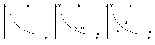
To illustrate this point, consider the example graph in Figure 1a. As it is unlabelled, one cannot tell what it represents specifically. One can, however, see that it may be ontologically interpreted in different ways. We might be tempted to read the line as representing a functional relationship between two variables. It is assumed that, given a value of X, a value of Y can be truthfully inferred by looking at the line. This interpretive scheme is shown in Figure 1b. Alternatively, we might interpret the line as representing a boundary between two regions of the graph, as shown in Figure 1c. In this case a different transformational operator is held to be truth preserving - knowing both X and Y allows one to infer either A, or B.
At least two different interpretive schemes apply and thus this form of representation can be considered to be inherently more ambiguous than the expression of knowledge as an algebraic equation. It is clear that equations of the form y = f(x) express a numerical relationship between two variables. The above example makes clear that this is not the case within graphs, unless labelled explicitly with the algebra. An important question to answer is thus what other interpretive schemes exist and can be usefully employed by the diagrammatic knowledge engineer. Little research has been directed towards such an answer. It rather seems the case, that each field of practice finds its own utility in graphs. Even in mathematics, the focus is upon the underlying mathematical model to be visualised, rather than the different ways a graph can be used to give representation to such knowledge. Despite our familiarity with Cartesian graphs, our sympathies lie with the opening quotation from Delacroix. Certain graphs are monsters; discerning the meaning requires additional lines of text that define an interpretive scheme.
The fact that the language of graphs can be exploited in very different ways, raises a important methodological question. How can we systematically determine what interpretive schemes exist and can be employed? Two issues must be resolved; one must
Research conducted within the Katcus project (Schreiber, 1995) provides a different solution to the problem of knowledge sharing that seems of benefit here. Rather than enforcing the standard usage of one ontology by all agents, an ontology mapping framework is surrected to allow knowledge to be re-conceptualised within different ontologies. This is achieved by defining rules that associate elements of one ontology with the elements of another. Such a solution provides for the re-usage of knowledge conceptualised within one ontology, for example, the Ontolingua frame ontology, to be exploited by problem-solving mechanisms that are grounded upon the structure of another, for example, an ontology specific to parametric design. In this case, a mapping rule might be constructed to associate, for example, the slot values of a frame, with the parameters of a design. In establishing connections between ontologies, the mapping rule framework also addresses the issue of how ontologies can be decomposed and usefully organised within a library. The ontology design principles introduced above are subjective in their nature. Whilst, in one context, the ontology appears over committed, in another it may be considered as under-committed. Whilst holding ontologies to be recursively embedded structures supports their hierarchical ordering with respect to semantic grain-size and dependencies, a mapping perspective allows ontologies framed from different 'natural perspectives' that can be related to each other in a principled fashion. The structure of an ontology library is that of an inclusion lattice from which components may be selected and related to each other according to one's needs. Such a solution is adopted, for example, by Borst (1997), who makes usage of EngMath components by defining mapping rules that associate physical quantities with the components of the PhysSys physical systems ontology.
The mapping framework is of value here as it allows a conceptual modelling ontology, to be related to an ontology expressing the syntactic components of a graph. A mapping rule can be defined, for example, between the lines of a graph and a functional relationship between entities. Such a mapping rule underpins the interpretation of the unlabelled graph above, Figure 1a. A set of mapping rules sufficient to interpret a graph defines an interpretive scheme.
Given the mapping framework is of utility in defining an interpretive scheme, let us consider the process by which different schemes can be generated. It is essential that each ontology, one specifying the syntactic components of a graph and another specifying the semantic components of a conceptual model, are fixed. Fixing these ontologies renders the space of possible schemes finite and thus subject to exploration. Exploiting the EngMath ontology as a conceptual modelling ontology seems to be a useful starting point for analysis. In making the semantic distinctions sufficient for the construction of mathematical models of the physical world, it makes the semantic distinctions sufficient for the interpretation of graphical representations of such models. The issue of what an appropriate ontology for the description of a graph remains more problematic. At this stage, we will merely employ an ontology that marks the visual distinctions, rather than the semantic distinctions, between components.
Whilst we could construct an ontology of diagrammatic components from scratch, it makes sense to make use of an existing ontology. The EngMath ontology provided the starting point for our analysis. It defines a quantity space, consisting of a set of points and a function returning the distance between them. We extend this to include a point of origin and functions to return horizontal distances of points from this origin. This minimal conceptualisation is usefully extended to the existence of lines and areas.
How a line is defined is somewhat problematic. Whilst a point is defined by an x and y co-ordinate position denoting the distance from the point of origin, a line can be defined in many ways that differ in their efficacy. We might, for example, represent a line as an explicit function relating Y co-ordinates to X co-ordinates (y = f(x)), or in parametric form (x=f(t), y = f(t)). Whilst this propositional approach underpins many mathematical visualisation tools, we consider it inappropriate for our purposes as it goes against the rationale of diagrammatic knowledge elicitation. We consider the definition of a line as a route towards a formal propositional representation, rather than a visualisation of it. The solution we adopt is to establish a definition that stands somewhere between a propositional representation and the low-level bitmap representation constructed by graph drawing routines. In the graph drawing tool we are currently developing, a line is defined as an ordered list of points that are interpolated by the B-Spline basis function. The definition of areas is also problematic. One could, for example, hold a closed curve to denote an area by defining its boundaries. We consider this to be inappropriate as a boundary may be defined by many component lines, We thus define an area as a set of spatial relations between points and lines, left-of, right-of, above, below, and within, that must hold true for all points the area subsumes. A certain area is thus denoted by the set left-of(point,line1), right-of(point, line2) and so forth. In addition to this, we include the notion of a text label associated with a point, line area or curve.
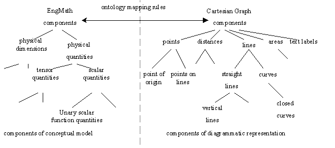
Given these two ontologies, depicted in figure 2, we will now explore the interpretive schemes that can be constructed to map between them. The compositional structure of the EngMath ontology supports such a process. We can consider each component of the inclusion lattice in turn and analyse the impact of the semantic distinctions they make. Such semantic distinctions themselves can be considered as framed within certain natural perspectives. The physical dimensions of a quantity represents one perspective, the distinction between scalar and tensor quantities represents another. Our analysis is thus structured according to what we perceive these perspectives to be.
Throughout the next section, we will illustrate the different interpretive schemes we define with reference to one particularly monstrous graph. The problem with the interpretation of such a graph is that the rules of interpretation do not map, in a one-to-one fashion between a class of diagrammatic primitive and a class of conceptual primitive. The reader is required to interpret two lines in two different ways. Indeed, the reader may interpret a single line in more than one way. More than one interpretive scheme is thus necessarily employed to make sense of the diagram. We term such graphs "composites". The frequency of composite graphs of this form is high - much more knowledge can be expressed within their content. The difficulty in their interpretation is substantial. Hopefully, our analysis reduces such complexities and substantially facilitates their utility as representational aids. Composites can be decomposed into simple graphs that are subject to simple interpretation within which a diagrammatic element is subjected to only a single interpretation, with a one-to-one relationship in the ontology mappings existing between the classes of object specified on each side.
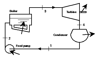
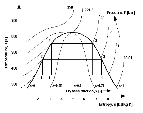
Figure 4 shows the "monster" composite graph from thermodynamics. Such graphs are used by engineers to solve different kinds of problems in this domain. University courses on thermodynamics include extensive instruction on how to interpret and construct graphs like this. The graph concerns the heat engine plant, shown in Figure 3, operating different cycles for generating power. Each cycle comprises four stages: the evaporation of liquid water into in steam in a boiler under pressure; the expansion of the steam in a turbine to produce power; the condensation of the mixture of vapour and liquid from the turbine; and finally the re-compression of fluid in a pump which is fed to the boiler to begin the cycle again. Water is a common working fluid. The graph encapsulates a great deal of knowledge. It depicts the physical properties of the water passing throughout the plant, such as temperature (T), pressure (P), entropy (s). The different phases of the water, whether vapour, liquid or a mixture of the two, at different times in the cycle is also represented. When the fluid is a mixture there is also information about the proportions of vapour to liquid, the dryness fraction (x). The graph represents the magnitudes of heat flow in different components and also the amount of power generated, which are shown as arrows in Figure 3. The characteristics of different cycles, including their performance efficiency can be compared. We will now proceed to decompose this complex graph into simple graphs. It will illustrate the interpretive schemes introduced in the earlier section. It will also demonstrate how a wide variety of types of knowledge are encoded and integrated in this single representation.
The only compositional property common to all graphs is the presence of two orthogonal axis lines. But can one define any firm interpretive rules for these primitives? Using the terminology specified within the EngMath ontology, it makes sense to interpret each axis as a physical quantity. Further, we might say that the physical quantities involved are interpreted as function quantities - they do not possess constant magnitudes but are associated with variance with respect to the magnitudes of other quantities. Thus, the interpretation of the X-axis, the horizontal distance, dx, of a point from the Y-axis is related, in a one-to-one fashion, with the magnitude of its associated quantity, and vice-versa, for the Y-axis and distances, dy, from the X-axis.
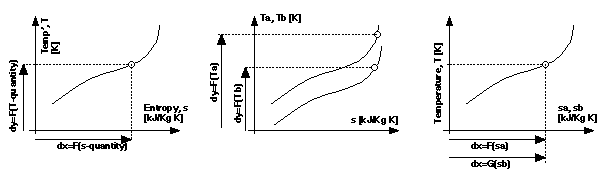
This leads to the generic interpretation shown in Figure 5a. A defined point within the graph becomes an instance of a functional relation between quantities, the points interpolated by a line stand interpreted as set of instances that define its extension, the geometry of the line providing its intensional definition. This will be taken as a universal interpretive scheme applicable to all graphs all graphs, but to do so the apparent exceptions in Figures 3b and 3c must be explained.
In Figure 5b, Y positions of each line stands interpreted as the magnitude of two different physical quantities Ta and Tb, so the Y axis seems to be associated with more than one function quantity of the same dimension. Figure 5c is similar to 5b, in that two function quantities, sa and sb, are associated with the single X-axis, but in addition the X position of a point, dx, is in both a one-to-one relationship with sa and sb and thus two physical quantities are denoted simultaneously. However, Figure 5a can still define a usable interpretive scheme, by considering graphs 5b and 5c as begin of composite form. Axes within them possesses more than one interpretation. They can thus be decomposed into simple graphs, like Figure 5a, within which each visual component possess a unique interpre tation in terms of the domain. Graphs of the form Figure 5b and 5c can be produced by overlaying two simple graphs, or inter preting a single diagram in more than one way. The decomposition of Figure 4 will follow in this manner, with simple graphs, each with temperature and entropy as X- and Y-axes, that are aggregated to make the composite. Given the universal rules of interpretation defined for the axes of a graph, attention now turns to the natural perspectives that determine the sources of variance in the way their additional components can be interpreted.
A major source of variance in the interpretation of a graph is the form of the functional relationships the lines it contains are held to represent. Different generic interpretive schemes can be distinguished following the way different classes of function are distinguished in the EngMath ontology. Different classes of functions can be defined according to the number of arguments they take - unary functions possess one argument, binary functions two, ternary functions three, and so on. Ternary functions are an appropriate upper limit as to the types a line within a graph can represent. Whilst the magnitudes of the two axis quantities are defined geometrically, the magnitude of a third quantity can be incorporated textually by labelling points and lines. Similarly, the magnitude of a fourth quantity can also be incorporated by textually by labelling the graph itself. The graph in Figure 6 can thus be held to represent a ternary function involving quantities T, s, P and M, which are temperature, entropy, pressure and the molar mass, M, of a fluid used in the particular plant.
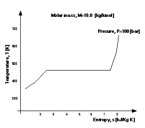
Obviously, this graph does not define the entirety of the function's extension. It defines only a subset, denoting only those mappings within which P and M possess a certain value. Additional mappings, those that are true at other values of P, can be denoted by incorporating more than one line (see below). Similarly, additional mappings, those that are true at other values of M, can be defined by drawing more than one graph. Aside from this informational deficit, the interpretation of Figure 6 is ambiguous, as it does not denote which properties are considered functionally dependent upon others. For example, is T to be viewed as a function of s, P and M? This would seem the conventional interpretation, as the Y axis is often exploited to represent the dependent quantity. Alternatively, we might hold s to be functionally dependent upon T, P and M. This is, in some cases, a matter of choice. However, certain explicit representational forms of an equation might not exist and this is reflected in the geometry of the lines. For example, the graph in Figure 6 cannot denote a function of s in terms of arguments T, P and M, because there is more than one magnitude of s for some values of T; the horizontal segment of the line.
Thus we begin to distinguish between and define generic graph types according to the type of function it defines (unary, binary and ternary) and which quantities are considered as functionally dependent upon others. The aim is to define, in graphical terms, the conditions under which a graph can be interpreted in terms of a certain functional form. If conditions are met for more than one form, then a single graph may be interpreted as an instance of more than one generic kind.
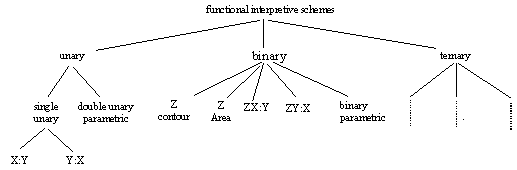
The types of functional relationship that can be depicted with a Cartesian graph are shown in the hierarchy in Figure 7. It reflects, from a propositional perspective, the different ways in which the functional relationship between two, three and four quantities can be expressed. From a graphical perspective, it reflects certain conventions concerning the interpretation of geometric figures and the textual labelling of lines. In the following subsections we examine each of the branches in turn, beginning with the unary branch, with examples of most of the types of graphs coming from the basic graphs that make up Figure 4.
The simplest graph is one that denotes a unary functional relationship between axis quantities denoting functions taking only one argument.
Unary X:Y Graph. Figure 8 has rules of interpretation that are intuitively clear. It must contain only a single line, with all possible states for which the relation holds falling upon that line. Conventionally the quantity serving as the argument to the function is associated with the X axis, whilst the function quantity is associated with the Y axis. This then imposes a constraint on the nature of the line. The X co-ordinate positions of interpolated points must always increase (or decrease) along its length; for every value of s there is a single value of T. We term a graph interpreted in this manner a unary X:Y graph.
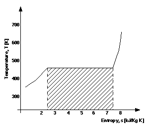
Further, the rules of interpretation of the gradients of lines is also clear, as are the gradients of tangents to curves, which represent the differential of T with respect to s, at a particular s value. Within the range 2.5�s�7.5 the gradient (dT/ds) is zero, elsewhere it is positive. Areas of a certain form within such graphs are subjected to integral interpretation. An integral area is the area directly under a given segment of the line to the X-axis. In Figure 8 the shaded area is an integral area bounded by the horizontal segment of the line, the s- axis, and upper and lower limits of s=2.5 and s=7.5, shown as dashed lines. Such areas are of interest to engineers, because its magnitude represents a quantity of heat, in this case the heat to evaporate the water in the boiler. Heat flows in the plant can be considered simply in relation to the basic quantities and the func tional relations among them. As we will see this makes Figure 4 useful for understanding the overall operation of the steam plant.
Unary Y:X Graph. When convention is broken and the X-axis quantity is held to be functionally dependent upon the Y-axis quantity, we have simple Y:X graphs. The rules of interpretation can thus be considered as reflected about the Y=X line. The Y co-ordinate positions of interpolated points must always increase along its length and so forth.
Simple unary function graphs are not common, as it is rare for a graph to contain a single line and for there to be no additional conditions known about the line or the graph as a whole. Compare Figures 6 and 8; whilst we might hold the temperature is a unary function of entropy at a certain constant pressure and molar mass, when these are not taken as constant quantities, temperature becomes a ternary function of all three (s, P, M).
Double Unary parametric graphs. Rather than depicting single unary function between the two axes, double unary paramertic graphs depict two unary functions between three quantities. This is done by making both axis quantities unary functions of a third quantity whose magnitude is represented by points along the line. Such double unary parametric graphs conform to the parametric representation of the function y = f(x). Such a graph, like unary X:Y or Y:X graphs contains only a single line. No constraints, however, exist as to the ordering of interpolated points in terms of their X and Y co-ordinate positions. Points are ordered according to the magnitude of the parameterising quantity, with its magnitudes represented by text associated with the points.
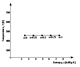
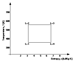
Figure 9 and 10 are components of Figure 4 that are unary parametric graphs. In Figure 9 the parameterising quantity is the dryness fraction, x, of the fluid, a ratio giving the proportion of fluid that is in the vapour state (zero means all liquid, unity means all vapour). The parameterising quantity in Figure 9 is location, L, and the label correspond to the labels in Figure 3: L=1, the fluid is entering the compressor; L=2, the water from the compressor enters the boiler; L=3, the steam is passing from the boiler to the turbine; L=4, the fluid has left the turbine and is on its way back to the condenser. For any given point/location in the cycle, the temperature and entropy of the water can be found and comparisons can be made between these quantities.
When it is possible to rewrite the relationship between Y and X quantities in terms of the explicit function y = f(x), it is clear that the graphical structure of many unary parametric graphs will conform to the conditions that sustain their interpretation as unary X:Y and Y:X graphs. Tangents and integral areas within such graphs bear the same interpretation in these cases. For example, the area under by the curve in Figure 9, represents the same quantity of heat as the shaded area in Figure 8. Further, areas within closed curves may be interpreted as cyclic integrals, such as the area within the curve of Figure 10, which happens to represent the power produced by the cycle, an important quantity.
Further, we can define vertical and horizontal distances between line-points to reflect the rate of change in X and Y quantities with respect to change in the parameterising quantities respectively. Computation of the rate of change, however, obviously relies upon the textually represented values of the parameterising quantity. For example, in Figure 9, it is apparent that the rate of change of s (X quantity) with respect to x (dryness fraction; parameterising quantity) is a constant, because the textually labels of x are increasing with equal increments and the labels are evenly space in relation to the s-axis.
When binary functional relationships are represented within the graph, it is clear that magnitudes of an additional third, Z, quantity must be represented as text. In the case of unary parametric graphs, such text is associated with points. In the case of binary function graphs the text is often associated with lines, but may be associated with areas. We consider the latter case first.
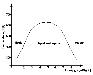
Z-Area Graphs. Lines in these graphs serve as boundaries between areas, rather than being interpreted as defining a functional relationship between quantities. The area is associated with a value of the Z quantity whose magnitude is textually denoted. Figure 11 shows a graph for the different phases, or physical states, of water that are relevant to the thermodynamics domain. Points falling within an area are interpreted as instances of a binary functional relationship between X and Y quantities and the Z quantity. In thermodynamics it is important to know whether the fluid is a liquid, vapour or a mixture of the two, at different magnitudes of T and s, because different pieces of equipment are needed to deal with water in each phase.
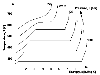
Z-Contour Graphs - XY:Z. When the Z quantity associated with the labelling of the lines is functionally dependent upon X and Y, we have Z-contour graphs. Z contour graphs contain multiple lines that are constrained so that the lines associated with different magnitudes of Z cannot intersect. Figure 12 can be interpreted as this type of graph, where for known values of T and s it is possible to find a unique value of pressure, P. Being able to find P from T and s for any point in a steam cycle is clearly useful. As required, the lines for P do not intersect. Whilst these are open curves, contour lines may be closed curves. Although all the contours have different values of P in Figure 12, in general Z contour graphs may have different contours with the same value.
It is inappropriate to regard tangents to lines as relating the differential of the functional relationship between X and Y quantities, because under a strict XY:Z interpretation there is no functional relationship between them. Similarly, it is inappropriate to interpret bounded areas beneath curves as integrals. (To exploit such graphical properties one must interpret the graph differently, see below.) Rather, areas within such graphs express known inequalities concerning the Z quantity. It is, for example, assumed that between two isobars relating the values P=1 bar and 5 bar, that 1 < P < 5, when no contour line falls between these isobars. It is implicit that sufficient contour lines are drawn to support such an interpretation. If the values of T and s do not fall on a line in Figure 12, an engineer can at least be sure of the range within which P falls, from the adjacent lines.
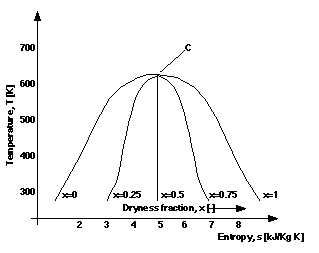
Binary Y(or X) Dependent graphs, ZX:Y (or ZY:X). For these graphs, it is the Y or X quantity that is held to be functionally dependent upon the others. For example, binary Y dependent graphs may look identical to a binary contour graphs. Indeed, a single instance of graph might stand interpreted as of both forms, such as Figure 12, but there is an important distinction between them with regard to the diagrammatic constraints. Two lines within a binary Y dependent graph cannot be associated with a label of the same magnitude of the Z quantity. The constraint that lines associated with different quantities cannot intersect, however, is now dropped. Consider Figure 13, in which the Z variables is dryness fraction, x. The graph must be interpreted as a binary Y dependent graph, because all the lines for each of the values of the third quantity intersect, at point c. In thermodynamics this is a special point with its own name, the critical point, because at this point liquid and vapour are indistinguishable and conventional steam plants cannot operate. Given values of s and x a unique value of T can always be found (ZX:Y, not ZY:X), but there is no guarantee that unique value of x can be determined from an arbitrary T and s values (not XY:Z), as they may correspond to the critical point.
Multiple points of intersection of the lines are common in other examples of binary-Y dependent graphs. Moreover, tangents to curves can now be interpreted in terms of the differential calculus, though they are not full derivatives, but partial derivatives at particular values of the Z quantity. Similarly areas beneath curves can be interpreted as partial integrals. (This is in contrast to the Z contour graphs above.)
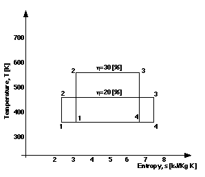
Binary Double Parametric Graphs. Like the double unary parametric graphs, a line in these graphs depicts two unary functions relating three variables, with the X and Y quantities being functions of a parameterising quantity whose magnitudes are associated with points on the curve. However, the double binary parametric graphs have more than one curve, with each possessing a textual label for an additional fourth variable. Figure 14 shows two parametric curves for different values of cycle efficiency, n, with corresponding location line-points in parametric form.
Ternary Graphs. In the hierarchy of graph types in Figure 7, the ternary node is left unexpanded as the subclasses of binary function graphs will repeat itself, with each graph having a textual label for the magnitude of an additional, fourth, quantity for the whole graph. For example, adding the label 'n=30 [%]' to Figure 10 changes the graph into a double ternary parametric graph.
The dimensionality of the X and Y quantities in a graph represents another important source of variance, the physical nature of the quantities. Quantities may constitute measures of mass [kg], temperature [K], pressure [bar], entropy [kJ/Kg K] and so forth, or be dimensionless, merely a number, as in the case of dryness fraction [ ] and efficiency [%].
As the areas within a temperature-entropy graph are of the energy dimension, one might treat 'T-s' graphs as being of particular generic kind. Similarly, we might define generic graphs whose axis quantities are of different dimensions. However, this is too low a level of granularity for the present analysis and would make the graph ontology over committed. At a higher level of analysis we need to distinguish between:
Figure 4 is thus an example of a dimensionally inconsistent graph. These distinctions are necessary for the interpretation of the distances within graphs. Horizontal and vertical distances can always be interpreted, because they represent the difference between two magnitudes of the X- and Y-quantities respectively. A distance possessing both a vertical and horizontal component, however, is obviously meaningless in the case of dimensionally inconsistent graphs. Computing the Euclidean distance involves the addition of X and Y quantities. Quantities of different dimensions cannot, however, be combined in this manner; they can only be multiplied and raised to powers. It makes no sense to consider the distance from point L=1 to point L=3, in Figure 10, but one can calculate the distance between points L=2 and L3. Within dimensionally consistent graphs, any distance is always of the dimension of the axes quantities and thus may prove meaningful. In the case of dimensionless graphs, however, the interpretation of distances is less than clear. One might, for example, regard such distances as measures of similarity and thus the meaningfulness of their interpretation cannot be ruled out.
A third important source of variance concerns the type of quantities the graph involves. Do the geometric positions and textual labelling denote the magnitudes of scalar quantities, tensor quantities or the scalar components of tensor quantities? When both axis quantities are regarded as scalar components of a tensor, are these quantities components of the same or different tensors? An important interpretive scheme is defined when both X and Y quantities are held to be the scalar components of a 2-D vector. In such cases, the distance from the origin becomes a meaningful measure, denoting the magnitude of the vector. Given this feature, polar co-ordinates can be usefully exploited, with points denoted by distance from the origin and angle of the vector to the X-axis. Such graphs are of an established generic type, being termed hodographs. For example, a hodograph denoting the vertical and horizontal components of the velocity of a projectile is a straight line, because the horizontal component (X-axis) does not vary. However, the distance from the origin to any point on the line is the overall velocity and the angle of the line to the X-axis is the trajectory of the projectile.
Whilst the above sources of variance relate to the relational mappings between a domain modelling ontology and the visual components of a graph, it is also possible to conceive of the semantic relationships that exist between different graphs themselves. Given these relations, the geometric features of one graph can be seen to map to the axis quantities of another.
A certain class of relation follows from examining the semantic relations between the components of the EngMath model. Derivative and integral relationships are the prime example. A unary function may be regarded as a derivative of some other function, or the integral of another function. Similarly, a unary X:Y graph may depict the derivative of some other unary graph, or the integral of another unary graph. For example, the areas enclosed by the curves for different values of cycle efficiency, in Figure 14, represent the amount of power generated. A new graph may be drawn with efficiency and power as the quantities for the two axes, and the particular curves in Figure 14 represented as points in the new graph.
A second class of relation follows from examining the semantic relations between the rules mapping between the EngMath and diagrammatic ontologies. Such relations prove crucial in determining whether simple graphs can be combined into a composite. We define three relations, aggregatable, partially-aggregatable, and overlayable that are grounded upon the physical quantities of the axis quantities and their dimensions.
Graphs between which the aggretable relation hold are those within which the same quantities are mapped to the same axes. This is what happens in the thermodynamics example, as all the graphs have temperature versus entropy axes. Graphs 6 to 16 are combined to form the composite in Figure 4. Because they are simply aggregated, the composite is a highly integrated representation for all the knowledge, enabling comparison between elements in the different component graphs to be made directly. This greatly increases its utility over a mere collection of the same simple graphs.
This straight-forward aggregation, illustrated in Figure 4, can be interpreted in the following way. At the most basic level conceptually, given any point in Figure 4, the temperature, entropy, dryness fraction, pressure, phase of the fluid, location in the cycle are all known. At the highest level it is possible to consider overall performance characteristics of different power cycles. From line segment for locations L=2 to L=3 of the curve for different parts of the plant (the unary parametric graph, Figure 10) we see that the heat absorbed by the fluid in the boiler occurs at constant temperature with increasing entropy and over a constant pressure (Figure 12, as Z-contour). This corresponds to a change from liquid to vapour (Figure 11, as Z-area) with a continuous increase in dryness fraction from zero to unity (Figure 13, as binary ZX:Y). The heat absorbed is the area under the horizontal segment of the line for a constant pressure of 5 bar (Figure 12, as a binary ZX:Y) and the heat lost in the condenser is the area under part of the horizontal segment of the P=1 bar line, in the same graph. The difference between these two quantities of heat gives the power output of plant, from which the overall efficiency can be calculated. The greater the temperature difference between the boiler and the condenser the higher the efficiency (Figure 14, as a double binary parametric).
In contrast, graphs that are partially aggregatable possess only one axis quantity in common. Consider Figure 12 and imagine another thermodynamic graph for the same power plant, but its X- and Y-axes stand for volume, V, and temperature, respectively. Such a pair of graphs that share one axis-quantity can be aggregated as above, but interpretations are constrained so that only distances in the Y-axis direction are meaningful. For example given a point on the T-s graph and another point on the T-V graph, the difference in temperatures between the points can be found. But the horizontal separation of points cannot be interpreted, as it is an arbitrary consequences of the particular axis scaling relations for the V and s function quantities. With respect to the common T quantity, the simple graphs are aggregated, but with respect to the other axis they are overlaid in an essentially unrelated fashion.
Finally, overlayable graphs are those that do not possess axis quantities in common, but whose axis quantities are of the same dimension. Depending on whether both axes, or just one, have the same dimensionality, distances in all directions, or just vertically/horizontally, may represent functional relations. The semantic relationships depicted are between the different quantities represented in each simple graph, rather than relations for the same quantity in the aggregate graphs.
The above analysis demonstrates the problem of interpreting graphs and the utility of an ontology mapping approach in exploring different interpretive schemes - the work of first phase of the DKA project. An Ontolingua specification of the diagrammatic ontology and mapping rules between this and EngMath ontology should prove non-problematic and is a goal we are working towards. This would provide both a standardised means of describing a graph and a library of rules for the knowledge engineer to exploit when interpreting what it represents. Here, we focus upon the implications of our analysis for the design of such tool and the methodology within which it will be used - the second phase of the DKA project on which we are currently engaged.
The first prototype version of graph drawing tool, that we have at present, is an electronic sketch pad especially constructed with the sketching of graphs in mind. Currently it supports a sketch-first, interpret-later elicitation methodology; an informal graph is first drawn and then formally interpreted by the engineer. It has been previously noted, that interpreting other classes of representation is a source of knowledge in its own right. For example, when interpreting a taxonomic hierarchy within the laddering tool of protoKEW (Reichgelt and Shadbolt, 1992, Shadbolt, 1992), it is not known whether the sub-classes of a concept exhausts the class or whether two classes are to be considered mutually exclusive. The knowledge engineer must be aware of these issues and a domain expert must be on hand to resolve them. The interpretive schemes generated through our analysis provides the knowledge engineer with such an awareness and forms the basis for a structured interview within which a complete, formal interpretation is acquired. Aside from supporting the engineer in this way, our analysis is also of benefit in the redesign of the tool to further support this draw-first, interpret-later approach to diagrammatic knowledge acquisition.
Our current tool does not reflect the layered structure of composite graphs exploited to resolve the complexity of their interpretation. Allowing different layers to be composed and assembled is thus one obvious extension. We highlight that this layered approach is not unique to our analysis, but reflects the way experts conceptualise graphs in many domains. This is often apparent in educational where complex graphs are introduced with a layered strategy to explain their content. Secondly, our analysis demonstrates that, in the context of certain interpretive schemes, our ontology of diagrammatic components is under-committed. For example, within hodographs, a distance between a point and the origin stands to be interpreted as the magnitude of vector. Within the current version of our graph drawing tool, there is no distinction made between this, and lines connecting two arbitrary points. Given the privileged semantic status of lines between points and the origin, it may prove beneficial to afford such lines a privileged status within the interface. We need to examine these sorts of commitment more thoroughly.
Whilst a sketch-first, interpret-later approach to knowledge acquisition is possible, an alternative is to exploit knowledge concerning how graphs can be used earlier in the process. The process of graph drawing may be usefully constrained in two ways. In the context of certain interpretive schemes, certain diagrammatic components and certain arrangements are rendered meaningless. For example, Euclidean distances cannot be meaningfully interpreted in a dimensionally inconsistent graph. Within this context, the user may be usefully prevented from defining such distances. For example, within a double unary (parametric) function graph, the textual values associated with points upon the line must be sequentially ordered, within a binary Z-contour graph, lines associated with different textual values cannot cross and so forth. Much stronger support might be provided if the user is prevented from semantically invalid arrangements.
Given that graphs can be used in different ways to represent certain aspects of a conceptual model, a choice exists as to which interpretive scheme to exploit. For example, given we wish to express the knowledge that both X and Y are unary functions of a third variable, is it better to sketch two unary functions in different graphs, or sketch one double unary parametric graph? The expression of knowledge may thus be promoted by examining the efficacy of different schemes in the context of different elicitation goals. The possibility of interrelating different types of graph by exploiting the semantic relations between them also presents itself. For example, it may prove beneficial when constructing a composite graph to focus initially on its component parts as a means to manage the complexity the acquisition of such a rich knowledge structure.
Our insights into the benefits of exploiting a knowledge of different interpretive schemes is at present limited. In this sense, our analysis raises more questions that it resolves. It is important to recognise, however, that such questions can only be asked having derived a stable ontology that establishes the choices that exist. Our analysis goes some way towards establishing such a stable ontology. Whilst it appears the interpretive schemes we define here can be usefully exploited to direct the process of elicitation, it must be stressed that this is an empirical issue. We thus plan to formulate and evaluate a number of approaches that differ in the number of constraints imposed during the graph drawing process.
Our current tool cannot yet impose such constraints. There is an implementation issue to be resolved. One might think that the problem of ambiguity in interpretation disappears when one refines the diagrammatic component ontology to reflect all of the semantic distinctions made here. One might consider extending the component library to visually distinguish between lines interpreted as Z-contours and those interpreted as unary functions and constraints as to their arrangement could then be hard-coded within the tool. Such a strategy fails to acknowledge an important point. It is impossible to specify a set of diagrammatic component classes that map, in a one-to-one fashion to components of the EngMath ontology as, within certain graphs, one component may be consistently interpreted in two different ways.
Two design solutions present themselves. On the one hand, we can define generic types of graph within which certain constraints apply and, subsequently hard-code such constraints within successive versions of the interfaces of the tool. Different interfaces would thus be exploited to construct unary function graphs, binary Z-contour graphs and so forth. This seems undesirable in this case for a number of reasons. Whilst it is possible from our analysis to define generic types of graph, the number of graph types that are definable, and hence the number of interfaces to construct, is high given the different, somewhat orthogonal, perspectives within which interpretive schemes are defined. It would thus be necessary to specify interfaces for a binary Z-contour hodograph, a double unary parametric hodograph, a dimensionally inconsistent double unary parameter graph and so forth. Secondly, the approach would not support the interpretation of a single component in more than one way or support dynamic shifts in one's interpretive stance when exploiting a draw-first, interpret-later approach.
The alternative is to construct a meta-tool within which mapping rules between diagrammatic and conceptual ontologies are softcoded, manipulated by the user and exploited by the system. Constraints would be provided indirectly, by exploiting the mapping rules to determine when any inconsistencies arise within the conceptual model under construction. Such a solution would be better when constructing new acquisition tools that focus upon different classes of diagram, and is constituting a substantial part of the engineering effort in the current phase of the DKA project.
Finally, we note that whilst we have addressed the problem of interpreting graphs, the problem has not yet be fully resolved. In particular, the problem of determining signal from noise in graphs was not addressed here. Should, for example, a particular line be interpreted as a quantitative unary function (e.g. Y = 2X) or a qualitative constraint upon a function (e.g. Y = F(X) is positively increasing with a constant first derivative)? We also stress that our analysis of directive diagrammatic elicitation methodologies is not complete. We need to perform this type of analysis with conceptual ontologies that are more committed, and thus more supportive of modelling, within more specific contexts. The results would not impinge so much upon the design of tool, but impact upon its usability. Providing more committed interpretive schemes may promote the expression of expertise by making clear how they can employ the structure of graphs to reflect the structure of knowledge.
Our analysis leaves many issues open and raises many more to be resolved. The framework of defining ontology mappings between diagrammatic and conceptual components provides us with a systematic approach to resolve these issues and construct diagrammatic tool kits that are more than sketch pads and that exploit substantial knowledge about diagrammatic knowledge acquisition.
This work was funded by a grant to Cheng and Shadbolt from the U.K. Engineering and Physical Science Research Council. Addition support came from the U.K. Economic and Social Research Council, through the ESRC Centre for Research in Development, Instruction and Training.
All authors contributed equally to this research.
Borst. P. (1997). Construction of Engineering Ontologies for Knowledge Sharing and Reuse. Phd Thesis. University of Twente. ISBN: 90-365-0988-2.
Cheng, P. C.-H. (1996). Diagrammatic Knowledge Acquisition: Elicitation, Analysis and Issues. In N. R. Shadbolt, H. O'Hara, & G. Schreiber (Eds.), Advances in Knowledge Acquisition: 9th European Knowledge Acquisition Workshop, EKAW'96. (pp. 179-194). Berlin: Springer-Verlag.
Cleveland, W. S., & McGill, R. (1985). Graphical perception and graphical methods for analysing scientific data. Science, 229, 828-833.
Davidson, D. (1974). On the very idea of a conceptual scheme. In Inquiries into Truth and Interpretation (1984). Oxford University Press.
Guarino N., & Giaretta P., (1995) Ontologies and Knowledge Bases: Towards a Terminological Clarification. In N. J. I. Mars (ed.), Towards Very Large Knowledge Bases, IOS Press
Gruber, T.R. (1993a) A translation approach to portable ontology specification. Knowledge Acquisition, 5: 199-220.
Gruber, T. R. (1993b). Toward principles for the design of ontologies used for knowledge sharing. In N. Guarino & R. Poli, (Eds.), International Workshop on Formal Ontology, Padova, Italy. Revised August 1993.
Gruber, T. R., & Olsen, G. R. (1994). An ontology for engineering mathematics. In J. Doyle, P. Torasso, & E. Sandewall (Eds.), Fourth International Conference on Principles of Knowledge Representation and Reasoning, Gustav Stresemann Institut, Bonn, Germany, Morgan Kaufmann.
Jones, S. (1988). Graphical interfaces for knowledge engineering: an overview of relevant literature. Knowledge Engineering Review, 3(3), 221-248.
Kosslyn, S. M. (1989). Understanding charts and graphs. Applied cognitive psychology, 3, 185-226.
Lohse, G. L. (1993). A cognitive model for understanding graphical perception. Human-Computer Interaction, 8, 353-388.
Pinker, S. (1990). A theory of graph comprehension. In R. Freedle (Eds.), Artificial Intelligence and the Future of Testing (pp. 73-126). Hillsdale, NJ: Lawrence Erlbaum.
Quine, W. V. (1969). Ontological Relativity and Other Essays. Columbia University Press.
Schreiber A., T, Wielinga, B., Janswiejer, W,H.J. (1995). The KACTUS view on the 'O' word. In J.C. Bioch and Y.-H Tan (eds) Proceedings 7th Dutch National Conference on Artificial Intelligence, NIAC '94, EURIDIS, Erasmus University, Rotterdam, The Netherlands, p. 159-168, 1995.
Reichgelt, H. and Shadbolt, N. (1992). ProtoKEW. A knowledge-based system for knowledge acquisition. In Sleeman. D and Bernsen, N.O Artificial Intelligence : Research directions in cognitive science. Vol 5. LEA.
Shadbolt, N. (1992). Facts. fantasies and frameworks, The design of a knowledge acquisition workbench. In Schmalhofer. F., Strube, G and Wetter. T (eds.) Contemporary Knowledge Engineering and Cognition. Springer Verlag. Heidelberg.