Overall
Design Document Department of Computer
Science Page maintainer: Terrence
Asgar-Deen |

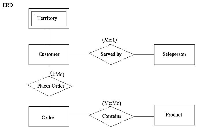
The purpose of the Entity Relationship Diagram is to illustrate the basic data abstraction and structure of the system. Each box in the diagram represents a single table of data that must be maintained by the system. This box is referred to as an "entity". The diagram above has have four entities which are Salesperson, Customer, Orders, and Products.
The information for each entity will be stored in a table where there is a column for each field. Each line in the table will represent an individual instance of the entity. For example, in the Salesperson table each line will represent one salesperson.
The Salesperson Entity table contains:
The "Customer" Entity table contains:
The "Product" Entity table contains:
The "Order" Entity table contains:
Each column represents an attribute in the entity. The italicized attributes with a "*" beside them are called key attributes. A key attribute is unique to each row and can be used to retrieve or delete information in an entity. Information can also be accessed by other attributes in each entity; however, the key attributes are unique and refer to only one instance of the entity. Non-key attributes can refer to one or many instances of the entity.
In the above ERD, the diamonds linking the entities are called "Relationships". The purpose of a relationship is to connect two or more entities in the diagram. All relationships in the above diagram link exactly two entities. The three relationships are served by, places order and contains.
The relationship "served by":
The relationship "places order":
The relationship "contains":
The box labeled Territory with the double bars around it is "Weak Entity". The weak entity divides the customers into their respective territories. This will ensure that each customer is assigned to the proper salesperson. The administrator will be forced to explicitly specify the territory in which a customer resides.